
Astromech Build-up Tutorial

This blog is set up as an in-depth tutorial for building up a lifesize Astromech from the kit parts seen here: (click on photos to view fullsize)

The sample kit showing in this tutorial can be seen in more detail here: www.goldenarmor.com/astrohomepage.html
With a set of kit parts, and the help of this tutorial, you will be able to create this:

Please keep in mind that these are KIT PARTS. They are untrimmed and will require some tools, time, and patience to complete. You should not attempt this kit without proper knowledge of garage kit building. That is, pieces may require extensive bondo and sanding applications. You should have power tools on hand to assist in these building stages.
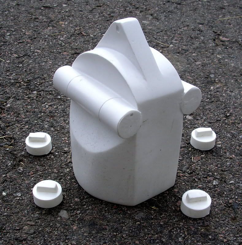
Here is a run-down of the kit parts:
- The Dome with various small resin detail pieces and lenses
- The Body
- Left Leg (with various detail components)
- Right Leg (with various detail components)
- Left Boot (with boot pins set of 2)
- Right Boot (with boot pins set of 2)
- Left Battery Pack
- Right Batter pack
- *(optional) middle boot
- *(optional) middle leg
An optional accessor is the drink serving tray and serving dispensor.

There are only 7 main stages (excluding optional electronics installation) to building up one of these kits:
- Trimming
- Cleaning seamlines
- masking
- painting
- bolting legs
- assembling details
- weathering
- *(opional) electronics - sound and lights
Let's start at the DOME and work our way down to the boots, and finish with some details on the optional electronics. Ready?!??
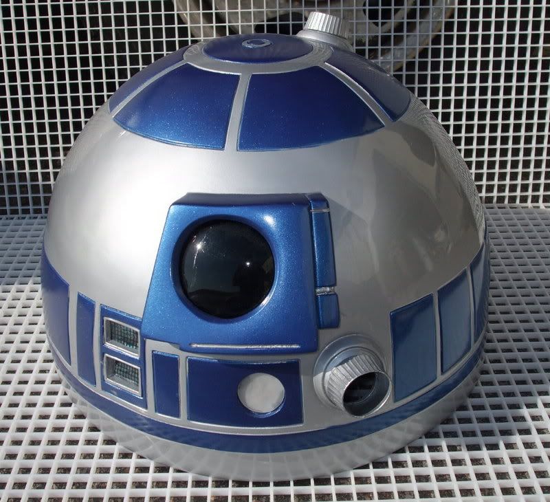
THE DOME


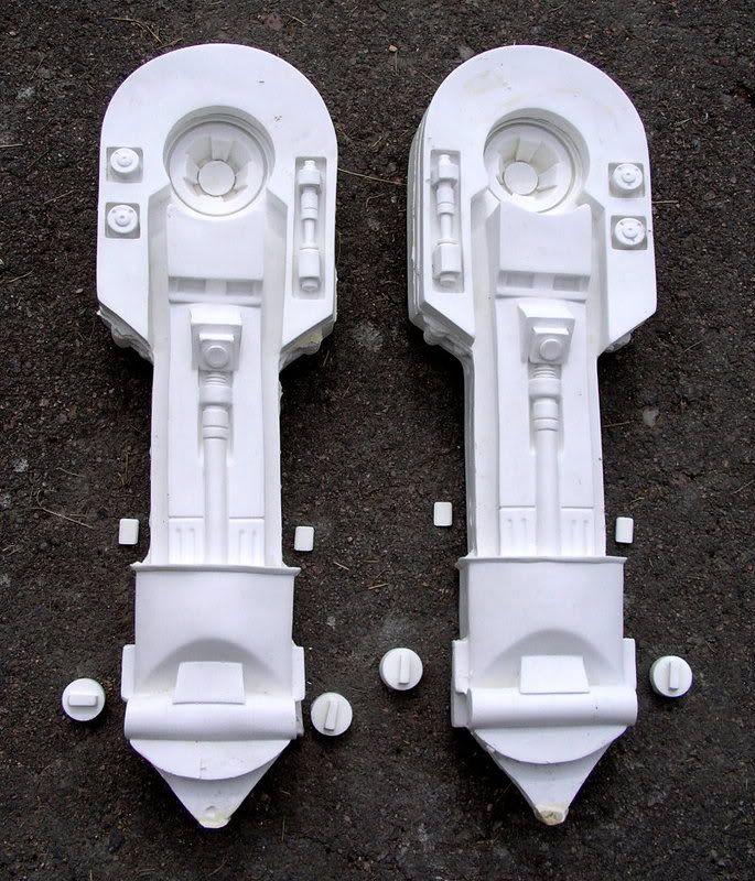
LEGS
Both the left leg and the right leg are composed of 5 pieces each. 1.) The main leg shell cast strong yet lightweight 2.) two detail chips 3.) two rod caps.


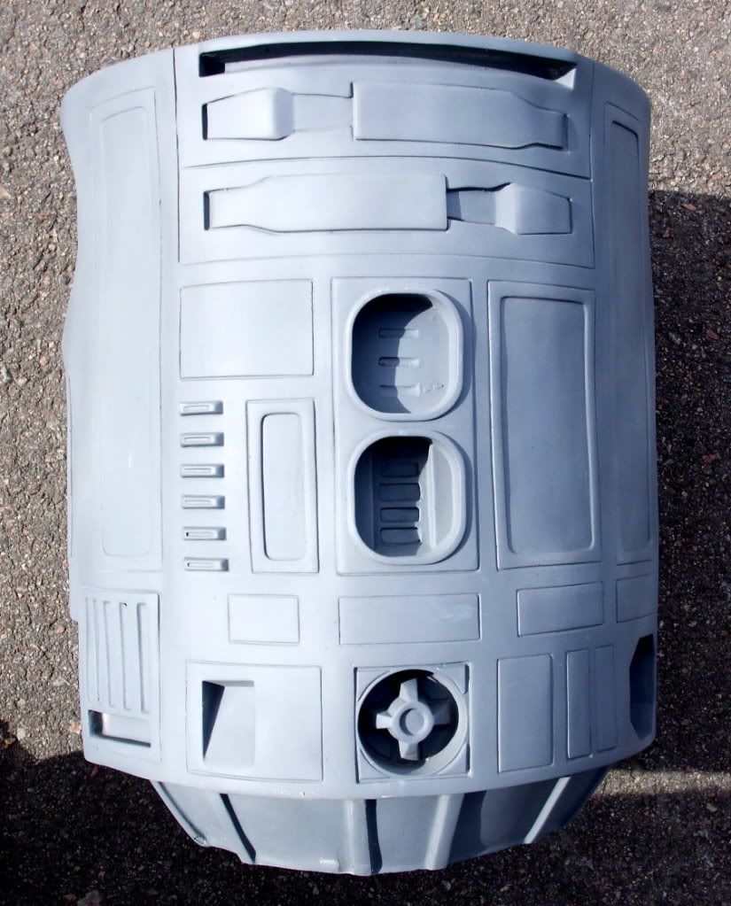
BODY
The body is a single piece casting, which will save you hundreds of hours of work compared to an aluminum skin kit set. You create the vents by cutting styrene pieces and glueing them in the slots. The body is cast in an 8 stage urethane/fiberglass matrix which keeps it hollow, lightweight and super strong.

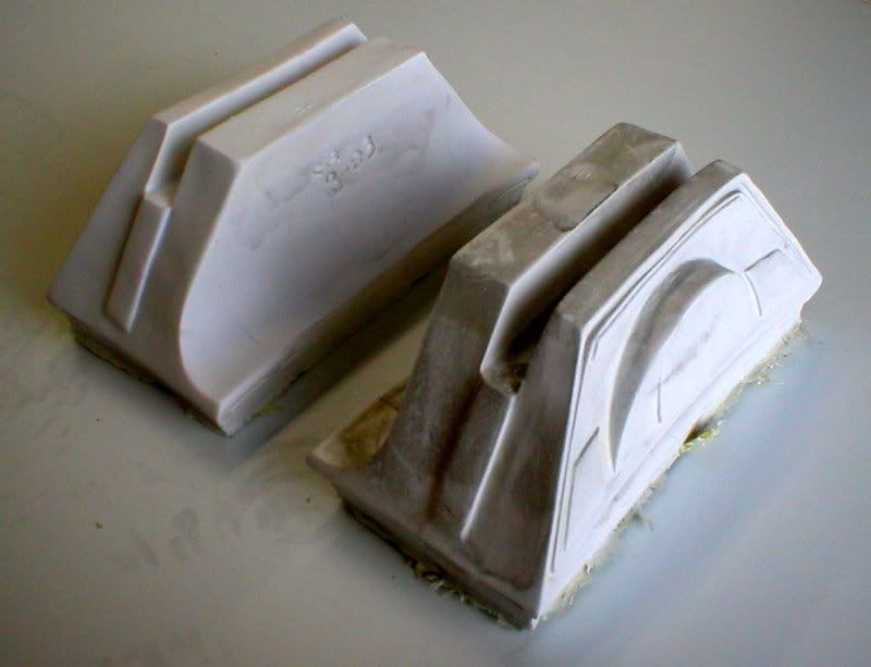
BOOTS
The left and right boots are made of hollow cast shells. There is enough interior room to install a motor and wheels if you're crafty.

BOOT PINS

BATTERY PACKS

MIDDLE LEG
The middle leg is composed of the middle boot, the leg component, and four rod caps.

____________________________
BUILDING TUTORIAL
DOME
Start with the dome by trimming the bottom edge on a belt sander. Use a dremel to remove the lense area to allow room to install the main radar lens. If you plan on installing electronics you'll need to trim the logic windows and lens to allow ample room for the light and transparencies. (see electronic options below). At this stage, you'll want to have the dome painted completely before you move on to further assembly steps.
LEGS
Start addressing the seamline on the legs by running a handheld sander over the seams. This takes much of the material out of your way. Use a dremel to remove some of the larger flashing around the side detail areas.

Next, spread some bondo across the seamline area, let it cure, then use your sander to start sanding away at the surface. Repeat these steps - bondo - sanding - bondo -sanding, until you have a nice flat, flush surface. Use a file to remove any flashing on the leg groove at the top.

It takes time and patience, but after repeating the trimming steps described above, you'll have two finished legs ready for the next assembly stages.

To secure the legs to the body, and have the flexibily to pose the legs at different angles, you'll want to embed a bolt into the shoulders as shown above. Start by drilling a hole in the center pit area. The hole needs to be larger than the head of the threaded bolt. Insert the bolt into the hole and fill the void with urethane or fiberglass resin, or simply pack it with apoxy. A little apoxie putty to re-enforce is show above. Don't worry about building a re-enforcing mound here. This will still fit flush on the body during your assembly phase (see below)
BOOTS
Each boot side is basically two pieces. The main shell, and the battery pack.


Spread some construction adhesive on the boot shell where the battery pack will contact. Press the battery into position, and then drive a screw through the pack into the boot as shown above.

The rear of the batter packs can be covered using styrene. Just trace the shapes of the packs onto sheet plastic, trim the shapes out, and apply with some adhesive. Your boots are FINISHED!

BODY
The body requires some crafty trimming and adjustment. An hand helt orbital sander will be your friend if you need to level the top rim, and reduce any diameter on the sides. Remember, bondo-sanding-bondo-sanding will cure anything.
Once cleaned, trimmed, and adjusted, there's only two things you need to do to prep the body. First is drilling holes into the shoulder joint area. This allows the bolt from the legs to pass through the body.

The second step is to install a plywood platform at the bottom of the body. Cut a strip of wood that sits on the inner skirt shape (shown above). This can be cemented in place with bondo, or fiberglass, or whatever adhesive you have on hand.
Now your ready for ASSEMBLY!
Before you paint your parts, you'll want to do a test fit of all the main parts. You can start by drilling the legs onto the boots.

The leg terminates in the shape shown above. Trim flatter as necessary so it fits into the boot and can pivot freely.

Drive a screw through the boot, through the leg, and into the boot shelf on the opposite side.
If you're building the middle leg option, do the same step as shown above. Drive a screw through the middle boot, through the middle leg pin, and into the opposing shelf of the middle boot.
Now you can attach the legs onto the body.

The bolt you embedded into the legs can now slide through the hole you made in the body. On the interior side, use a square of wood, a washer, and then a wingnut to tighten the legs onto the body as shown.
Your result will be:
And with the Dome in place:
PAINTING
The dome is painted SILVER, everything else is painted GLOSS WHITE. All surfaces should be gloss-coated (automotive lacquer works well). Now that your parts are painted, you can begin masking the different color sections.

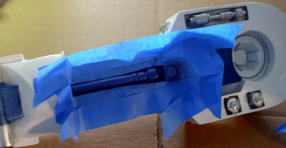
For the middle leg, mask off the cylinders which will be SILVER (showing above)


The legs involve a bit more masking work. There are BLUE and SILVER areas that need to be masked. This can be done in any order Here you see the silver areas being masked. Once painted silver, they are masked over, and the blue is applied.

There are small details on the leg that are silver and blue overlayed on their opposing colors. This can be done by hand with small brushes.
If you encounter overspray, don't fret. The silver, blue and white can be easily touched up with matching colors.
Now mask off the center leg piston and paint silver.
While you have all the masking in place, paint the center of the shoulder like this:
The boot separation plate and side details can now be painted silver. (showing before and after below): The center blue leg post requires some silver detailing (applied with a microbrush). Showing below: The detail chips (blue) can now be applied as well as the silver endcaps. Masking and detailing the body is done the same way. Mask out the silver and blue panels carefully. 


The 'coin slots' are blue, with silver tops (hand-painted).
The front vents are painted silver. Flat styrene can be cut and glued in place to create the individual vents.
The side panels are two tone - silver and blue. Once the silver is spraypainted, use more painters tape to mask out the slots and paint blue.


DOME

Scuff the exposed panels with a scotch-brite pad and then paint the panels BLUE. Kyrlon (rattle can) COBALT BLUE METALLIC is a great match.

The logic port window frames must be hand painted silver. Do this with a microbrush and silver enamel paint.

There is some small silver trim applied on the radar lens housing (showing above).

The Dome has two little buttons in the rear. Dot this with black paint.
The above and below photos show some additional silver detailing applied to the dome. The Radar lens is a clear piece of thermal formed PETG. Spraypaint the interior BLACK. When viewed from the front, it will appear glossy black. Hotglue this lens into the interior of the lens housing (showing below). Now glue the emitter caps in place.


COMPLETED ROBOT (3 legged pose)
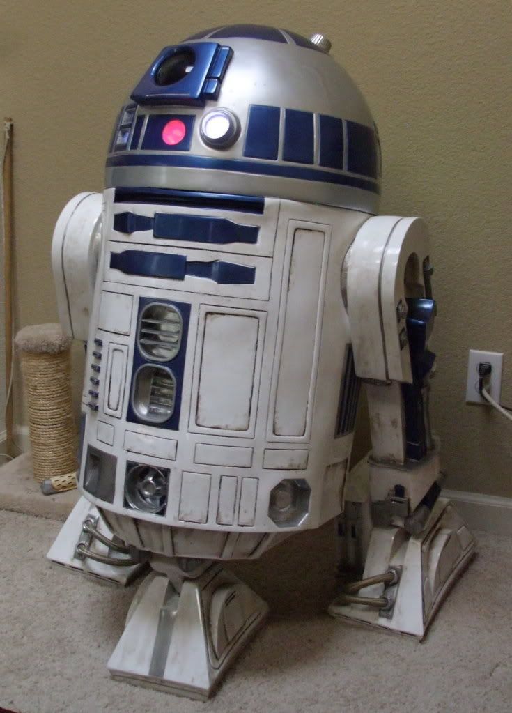
COMPLETED ROBOT (2 legged pose)
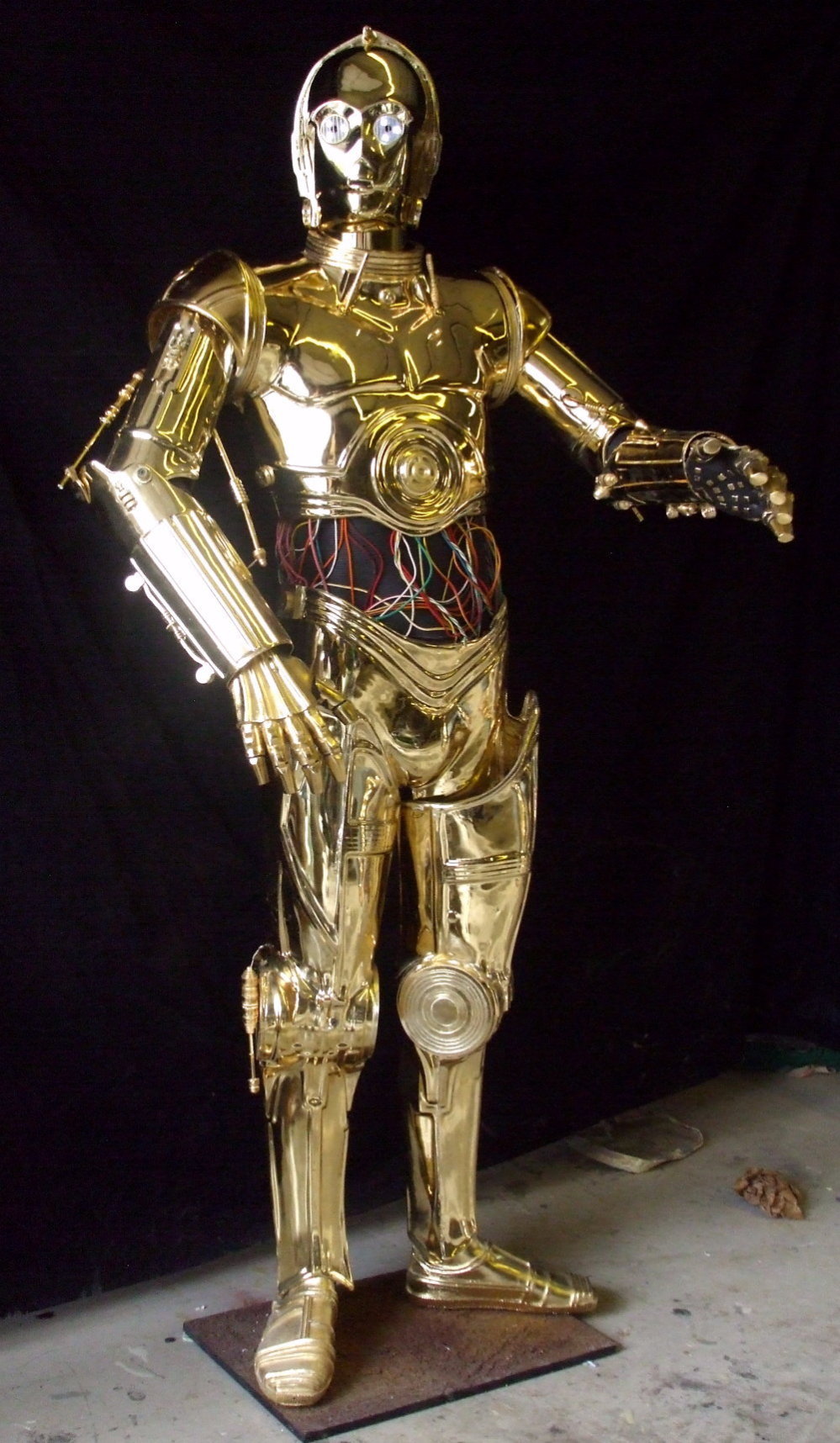
BE SURE TO TAKE A BREAK AND VISIT:
ASTROMECH ELECTRONICS
You can accentuate your buildup with electronics. I'm not very proficient with servoes, motors and actuators so I limit my electronics to lights and sound. Here's some details about some light options for this droid:
These are laser cut acrylic grids patterned EXACTLY to the transparencies provided with the dome kit.

The matched 1mm holes correspond with each of the color dots in the logic transparencies. Here's how to utilize this: First you need a logic display circuit. It comes to you pre-wired, attached on a battery clip and on/off toggle so all you need to do is bundle then and attach some 1mm fiber optic filament (not included). Showing here:

The LEDs flash in random patterns. We can take advantage of this organic pattern by attaching fiberoptic filament.

NOTE: the logic circuit is available by emailing impervium@hotmail.com You will need two of these logic circuit boards to create the lighting for both the front and rear logic ports.
The photo below shows how you can bundle the fiberoptics into small tubes. You can stuff up to 11 fibers. These bundles are then glued onto each LED separately.

The photo below shows a single bundle as it is being randomly distributed in the rear logic port. Once you poke a fiber through, use a lighter to slighly heat the end of the filament. This will cause the end to mushroom, preventing it from pulling out completely.


What you see demonstrated here is about 9 1mm fiberoptic filaments attached to EACH LED. With 9 LEDs this creates 81 points of light. When bundled randomly into the laser cut logic grids, the effect is beautiful.
This shows the array configured to the REAR LOGIC port:

This shows the array configured to the FRONT LOGIC ports.


The on/off toggles can be hidden inside the top emitter. This provides easy-access to the switches.

The Dome demonstration seen below utilizes: 2 logic emitter boards (9 LEDs each bundled with fiber), a red/blue flasher, and a green/yellow flasher. Email IMPERVIUM@HOTMAIL.COM to order your light packages.

VIDEO DEMOS HERE:
Reader Comments