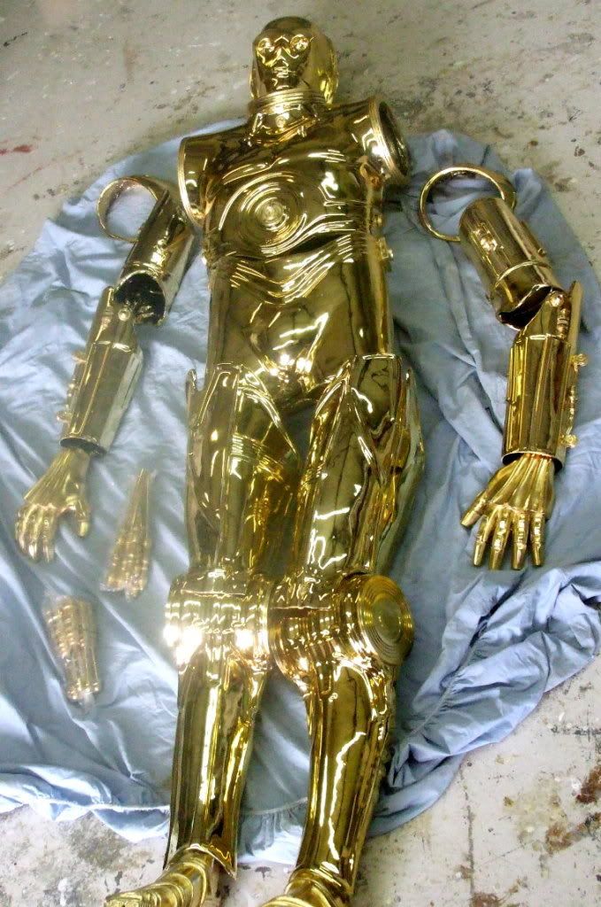
Protocol Droid Build-up Tutorial
 Thursday, December 10, 2009 at 7:15PM
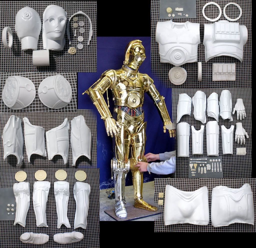
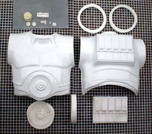
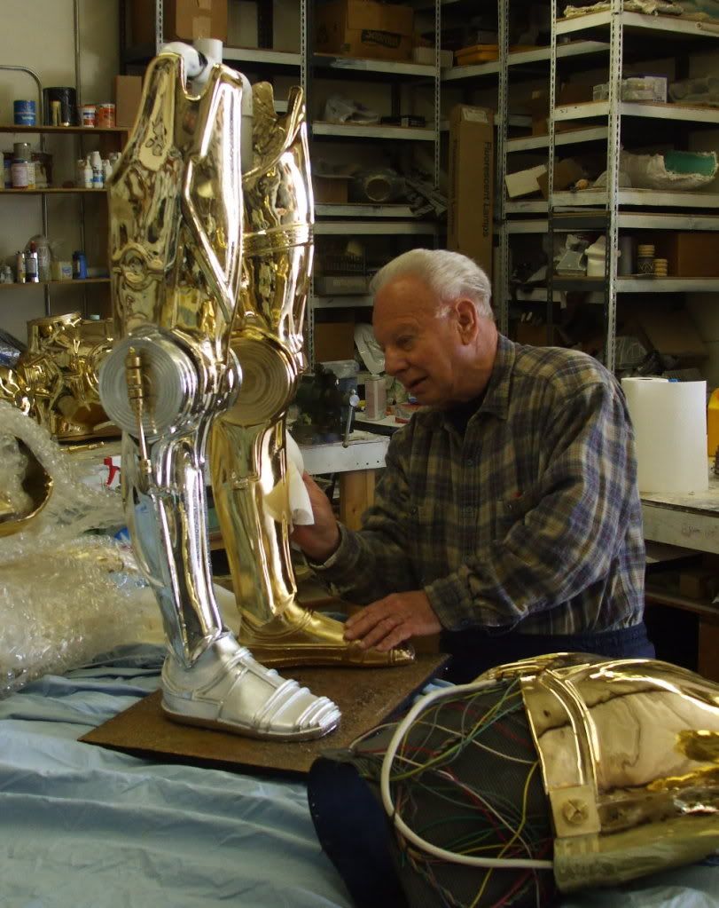
A full head to toe kit looks like this: (click for fullsize views)
You'll notice that many of the body components of this kit are thermal formed shells that have been designed with missing 'high detail'. The 'high detail' areas are any surfaces that have hard edge ridges, rings, ribbing, piston protrusions, knobs, etc.. These details are separate hand-cast urethane parts. Once assembled, accuracy is completely maintained.
This technique was achieved to assist in the gold chroming process (thermal formed shells are the best substrate for gold chroming processes).
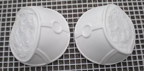
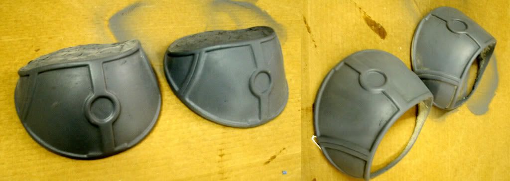
The rundown of the RESIN-CAST components are as follows: Horseshoe head ring, head bolts, head antenna, rear head port, eye grills, eye cups (transluscent), neckring, shoulder rings, both shoulder bells, abdominal ring, chest knobs, hip detail bricks, knee disks (4 total), feet, both hands, and an assortment of detail pieces composing the full piston and actuator sets for the legs and arms.
There are 12 main stages of assembly on this kit.
-
Trimming
-
Assembling shells
-
Re-enforcing shells
-
Final trimming
-
High detail
-
Attachments (armature assembly, magnetic armatures, wire armatures, etc..)
-
Piston/Actuator construction
-
Mid-section assembly
-
Building the display base
-
Final assembly
-
Painting/Plating
-
Optional electronics (lights & sound)
Tools needed for these steps include: Belt sander, bandsaw, power drill, sandpaper of various grits, dremel with various bits, CA glue with spray kicker, bondo, pvc cement, gorilla glue.
Materials needed (not included in the kit): apoxie sculpt (aves supply), rubber sheeting (ace hardware), wiring (radio shack), mdf board (home depot), 1" pvc stock and 1" pvc joints (home depot), sheet metal, wood screws and bolts (home depot), and 3" magnetic disks (available online).
We'll start with the head and work our way down to the feet. Here we go!!!!!!!!
THE HEAD
I had previously posted a head buildup tutorial here: www.goldenarmor.com/vacheadtutorial.html so please refer there if you have any questions from this blog.
Let's start by looking at the kit components:

The head kit consists of 2 thermal formed shells comprising the face and back of the head, a horseshoe ring, neckring, 2 neckbolts, an antenna, 2 eye grills, a rear head port, PVC neck, and 2 transluscent eye cups.
|
Once your horshoe ring is in place, glue the rear headshell in place using superglue and spray
kicker. There may be a few areas that overlap beyond the horsehoe. Trim those areas away with a dremel. Now fill in the gaps with bondo. |
into place
The trimming on the shoulders is very simple. Accomplish this on a belt sander. I use a 36" belt sander but you can do this with a smaller machine. First trim the flashing off the bottom. The rough trim the flashing in the center with a dremel (cutoff wheel attachment), then finish on a drum sander. That result will look like this:
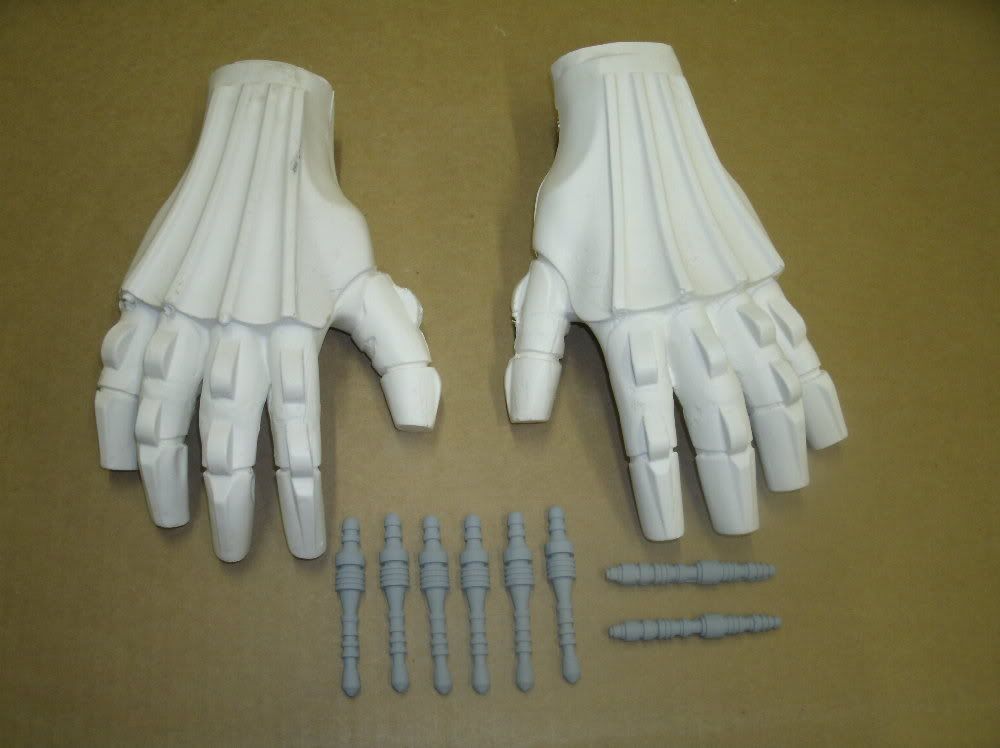
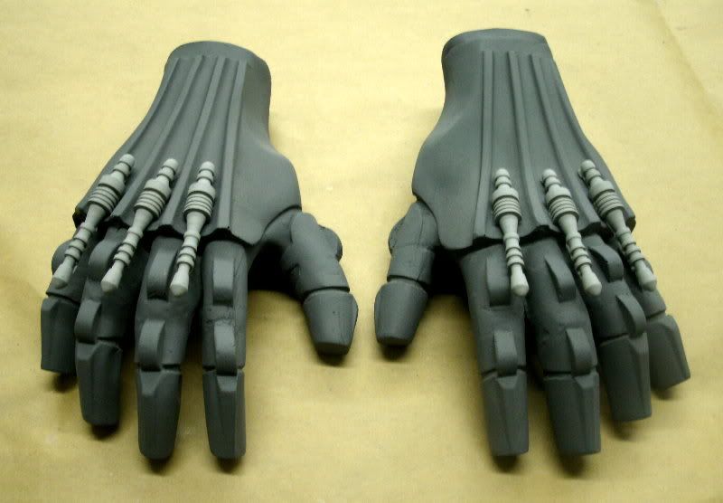
Each hand is 4 pieces(unless you're getting the wearable hands): a lightweight casting with 3 knuckle pistons. Use bondo and putty to fill any showing seamlines and move foward to:
ARMS
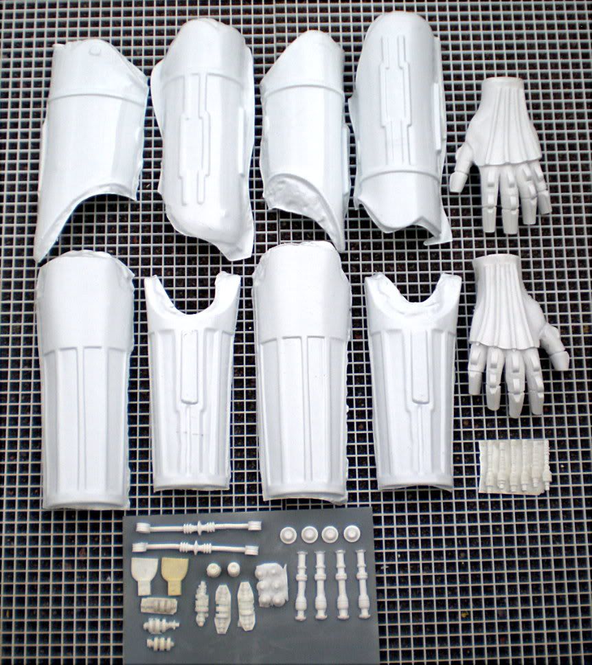
With the arm shells i'll show you the construction of the biceps separataely from the forearms. First the biceps:
When trimming the biceps, you can adjust the width of the final pieces by using a heatgun to reshape the countours. A few of the parts need adjusdment using this technique anyways but if you are going for a wearable suit, you can adjust them in even further to make skinnier pieces.
One you have the two shells on each side, user superglue and spray kicker to spot glue them into position. Now cover the interior seamlines with bondo, then PVC cement over the top to adhere the bondo to the plastic. Be sure to wipe off any excess PVC cement as it is caustic to the plastic surface. Once all this is dried you will have a VERY secure adhesion.
Like the biceps, the forearms need a little adjustment and, if you are making a wearable costume, customization to your body size. This is done using a heatgun. Be careful not too apply too much heat at once. Test your heatgun on some scrap plastic before proceeding. Once you are happy with the size, spotglue (CA glue and spray kicker), and hold in position with clamps until the glue is dried. Apply bondo, then pvc cement to the interior seamline for ultimate strength.
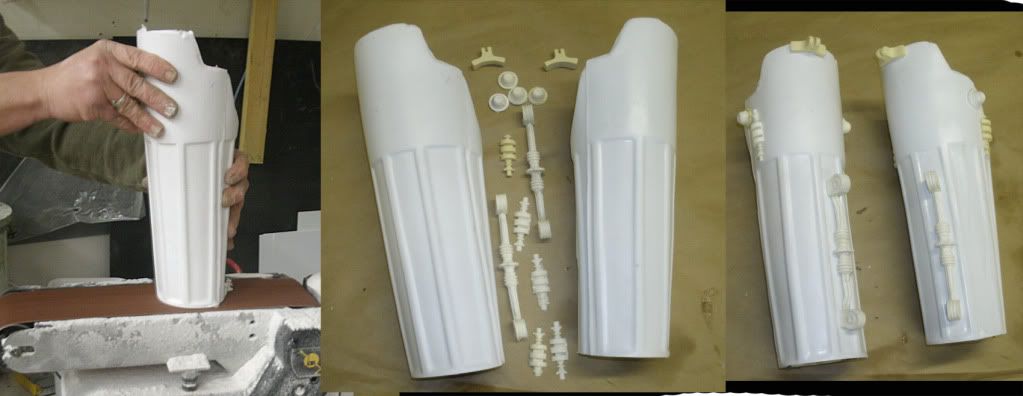
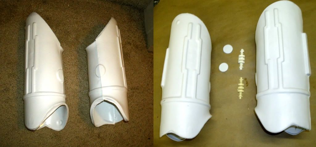
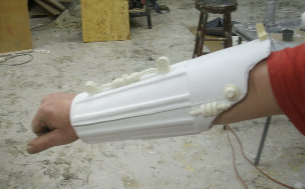
Next, trim the parts on a belt sander (showing above) and begin assembly using the provided resin detail components.
The above photo shows the new groove plates, forearm knobs, and piston attachment pins and how they are assembled on the forearms.
If you are converting this to a wearable costume, you can see that the arms, assembled according to the steps above, need no modifications. They can be custom trimmed and lined with foam for comfort.
_________________________________
ARM PISTONS
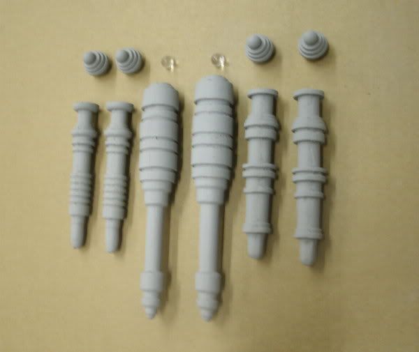
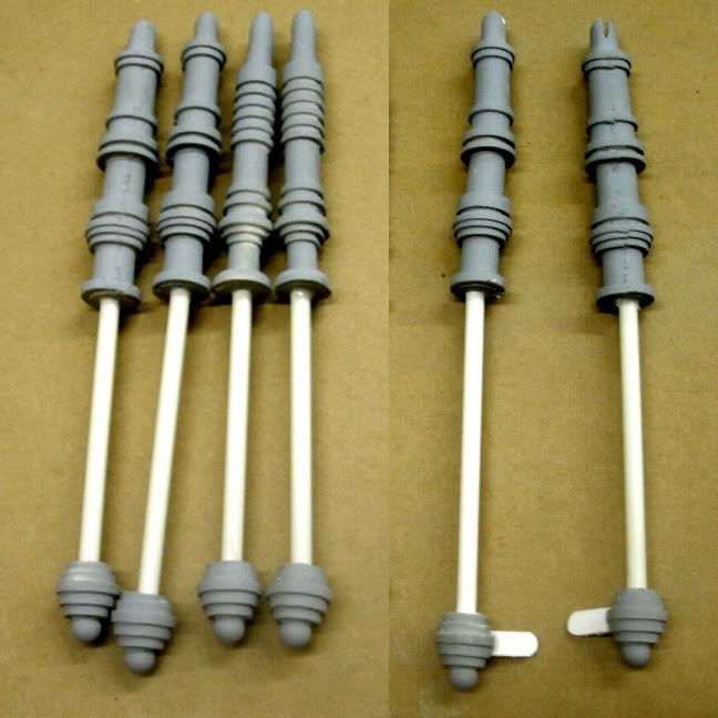
These are the arm pistons (resin cast) provided with the kit. You can feel free to upgrade these with brass or aluminum rod pistons from a machine shop. But these are free of charge with each kit. Start by attaching the glass marbles onto the knee pistons, then, after you clean the parts with sandpaper and files, use a drill to assemble wood or plastic rods in place like this:
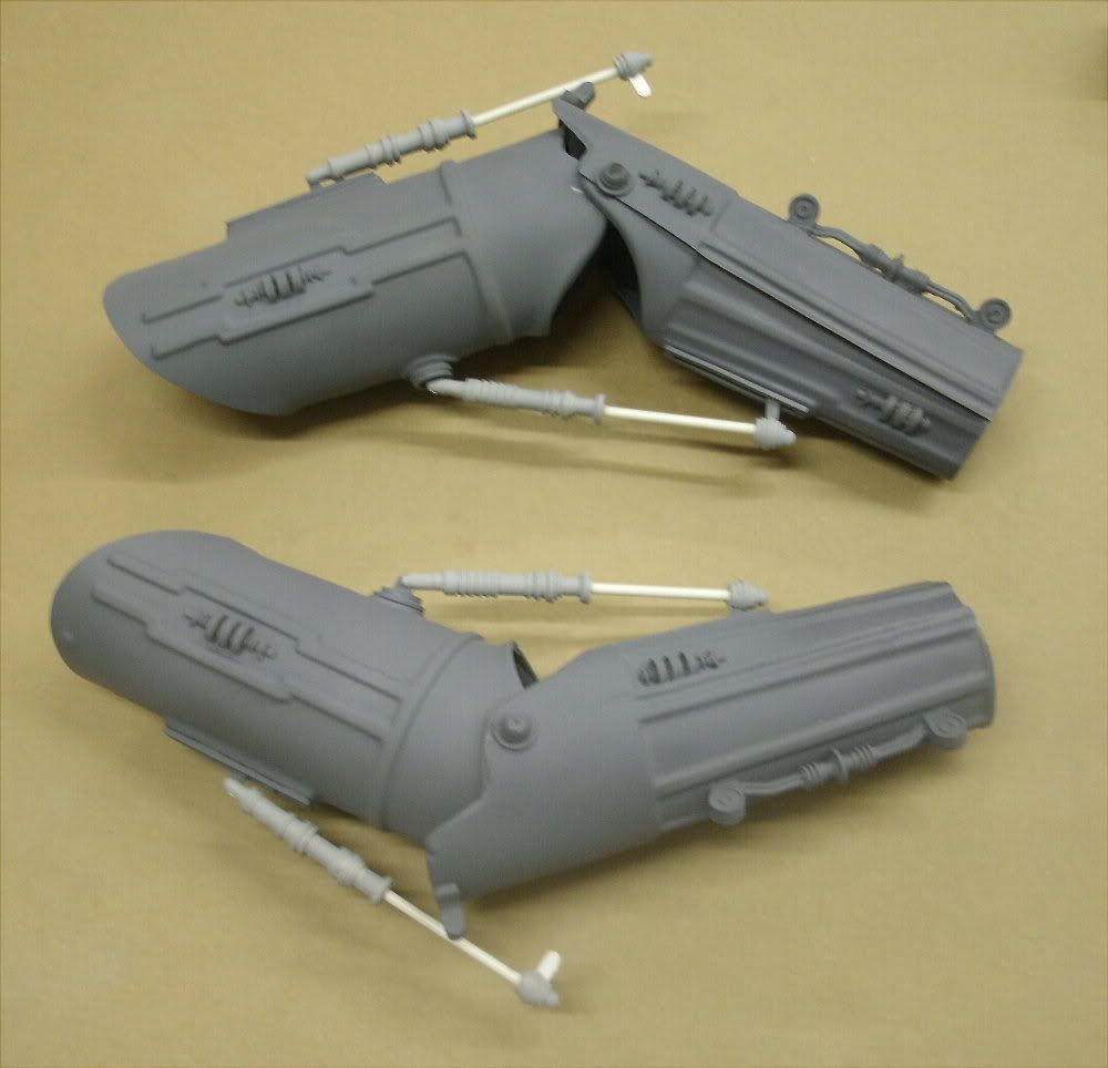
The INNER arm pistons attach at bicep using a cleaved open end (cleave it with a dremel cutoff wheel). The lower portion attaches at the forearm.
The OUTTER arm piston attaches with a cleaved pin attachment at the top, and a tongue and groove attachment at the elbow.
I left the piston rods untrimmed at the ends (with removeable attachment knobs). I left them much longer than is needed so I can custom pose the arms once the components are gold plated. Once a desired length is settled, you can trim the pistons, or leave the rods unglued so they are functional (slide in, slide out).
TRUNK
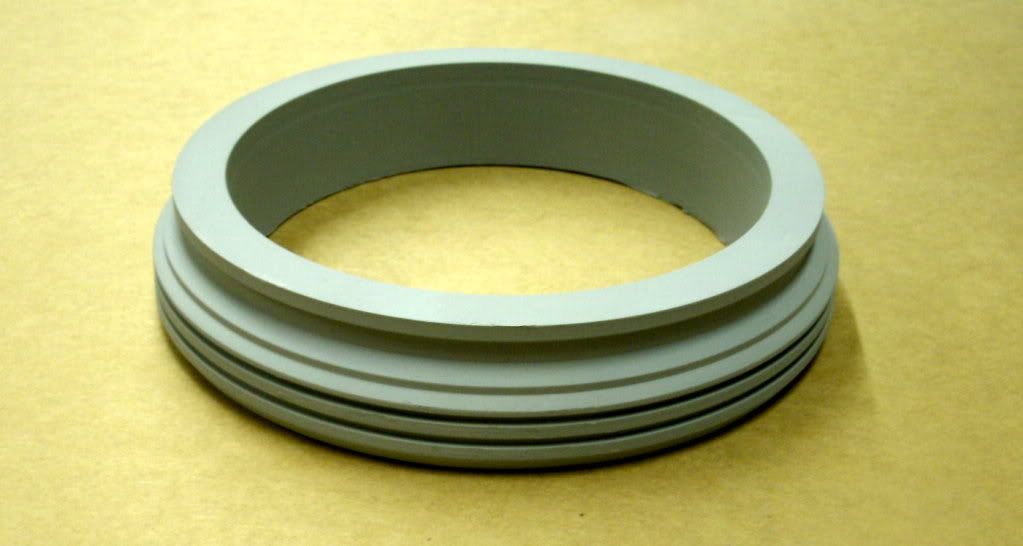
March 2010 UPDATE: This is the NEW NECKRING!! Turned by my friend Dennis at his machine shop in Colorado.
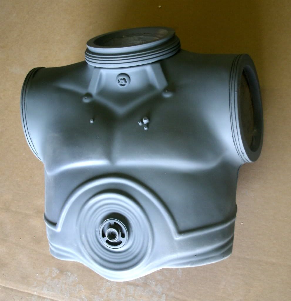
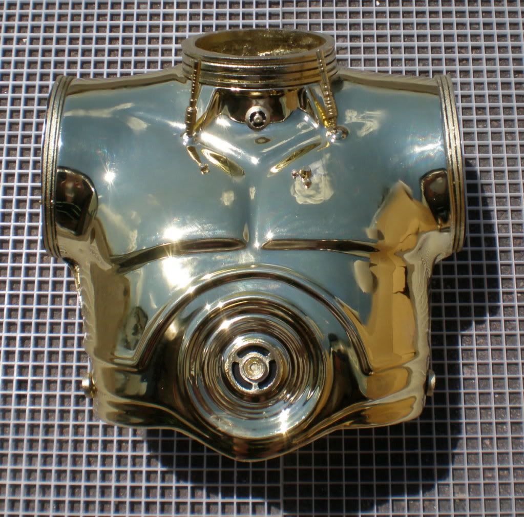
First start off by trimming the flashing off the sides, tops and bottoms of the trunk shells. When assembling them together, if you overlap, overlap the front over the rear (showing in these photos). Use the shoulder ring and neckring to ensure you are assemblying properly. There should be enough room to allow these rings to sit on top of the assembled diameters. Hold them in position with tape and spot glue them with CA glue and spray kicker, followed up by bondo and pvc cement for strength.
Note: when you assemble the trunk halves, have one of the resin shoulder rings and the neckring on hand. You can use these to make sure you're leaving yourself enough room for them later.
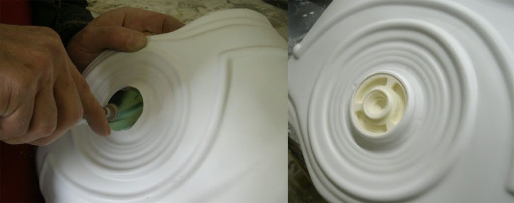
Dremel out the 'belly button' using a drum bit and inset the detail piece from the inside (see above).
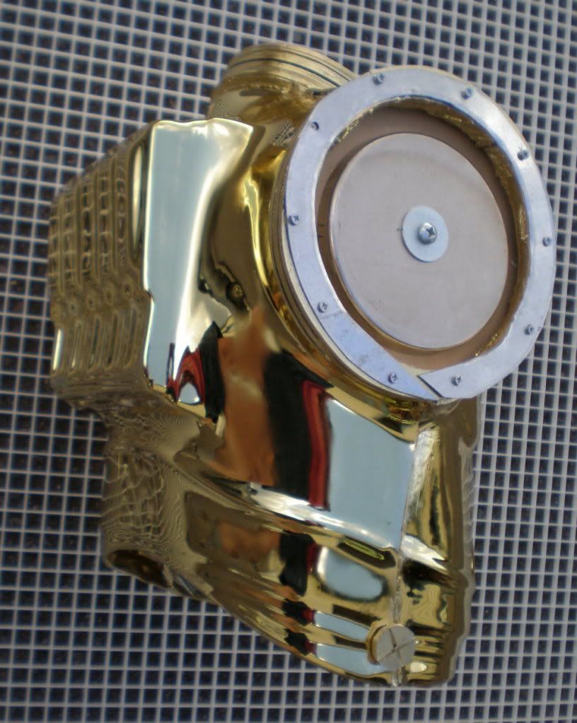
Use your belt sander to trim down any excess plastic that raises above a flat surface level for the shoulders. The shoulder ring must lay flat. Once you are satisfied with the trimming use CA glue and clamps to hold the rings securely in place and spray kick them to make the bond permanent. The last photo showing above shows the placement of the chest detail pieces.
At this stage, use painters tape to secure off the seamlines on the shoulder rings. Cut two plywood disks that fit the interior of the shoulder. Use liberal amounts of bondo over the interior seamlines and press the wood disks deep into the shoulder. This provides for stength and also a mounting plate for your shoulder mangetic ring attachment. (see below)
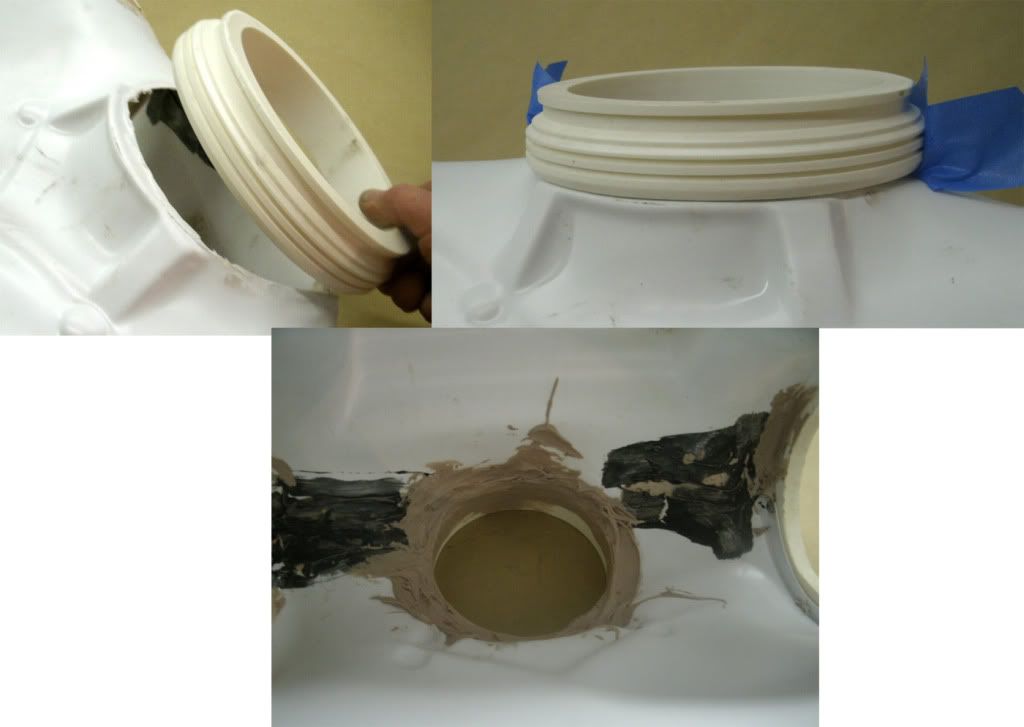
Attach the NECKRING the same way you attached the shoulder rings. Trim the area flat on a belt sander, spotglue the neckring in place, cover the entire area with painters tape and backfill the INTERIOR with bondo to cover any gaps. A combo of bondo and aves apoxie sculpt will take care of any gaps (needed at the rear to blend the neckring into the backplate).
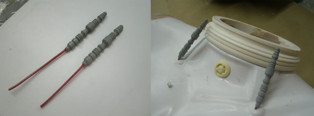
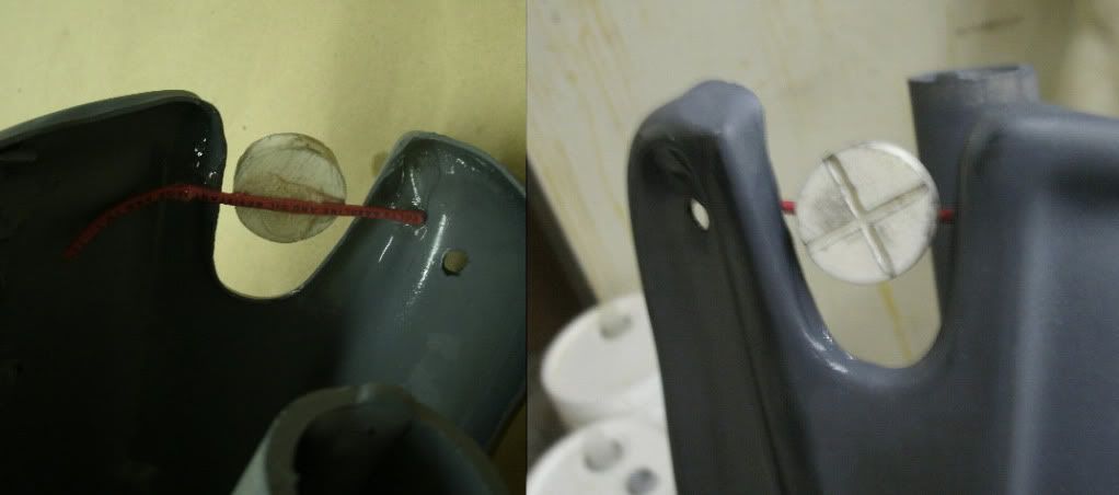
The 2 throat pistons attach like this (showing above). The rods do not lay against the neckring at all, they hover away from them, pointing upwards. Do this by attaching wire to the ends and feed the wires through the throat area. On the interior, bend the wires upwards so the tension holds the pistons up and away from the neckring. Use adhesive to seal their position. The throat medallion can now be glue in place also.
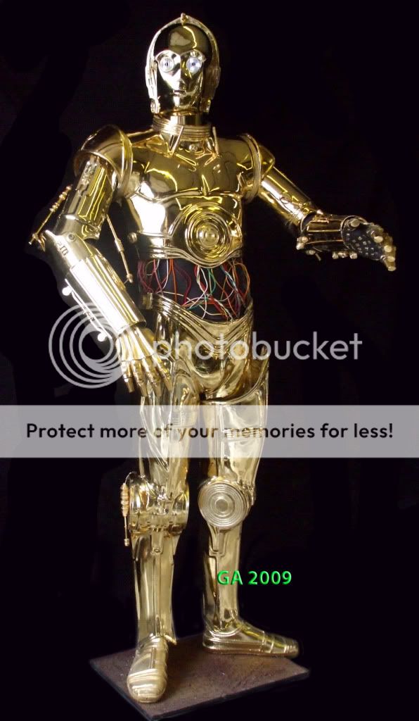
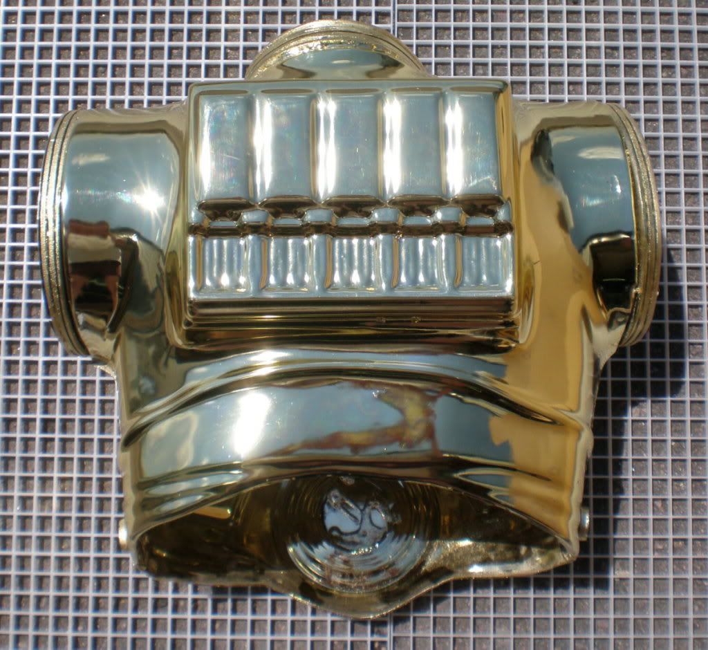
COMPLETED TORSO!! (minus the throat pistons which will be attached after gold plating is completed).
HIPS
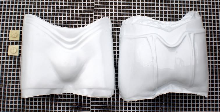
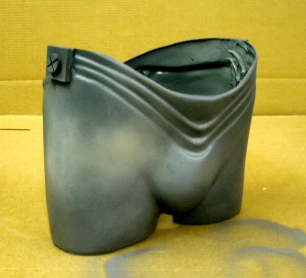
The hips are very simple. They are composed of 4 parts: Front shell, back shell, and two detail pieces. Start by trimming the flash off the hips. The FRONT overlaps over the rear so leave plenty of flashing when trimming the rear hips.
Use clamps to hold the halves together and superglue/spray kick to adhere, then follow up with bondo and PVC cement. The detal bricks are trimmed nad glued on the sides at the tops. The gaps can be filled with either bondo or aves apoxie scupt (my favourite since you can sculpt it in and reduce your sanding time).
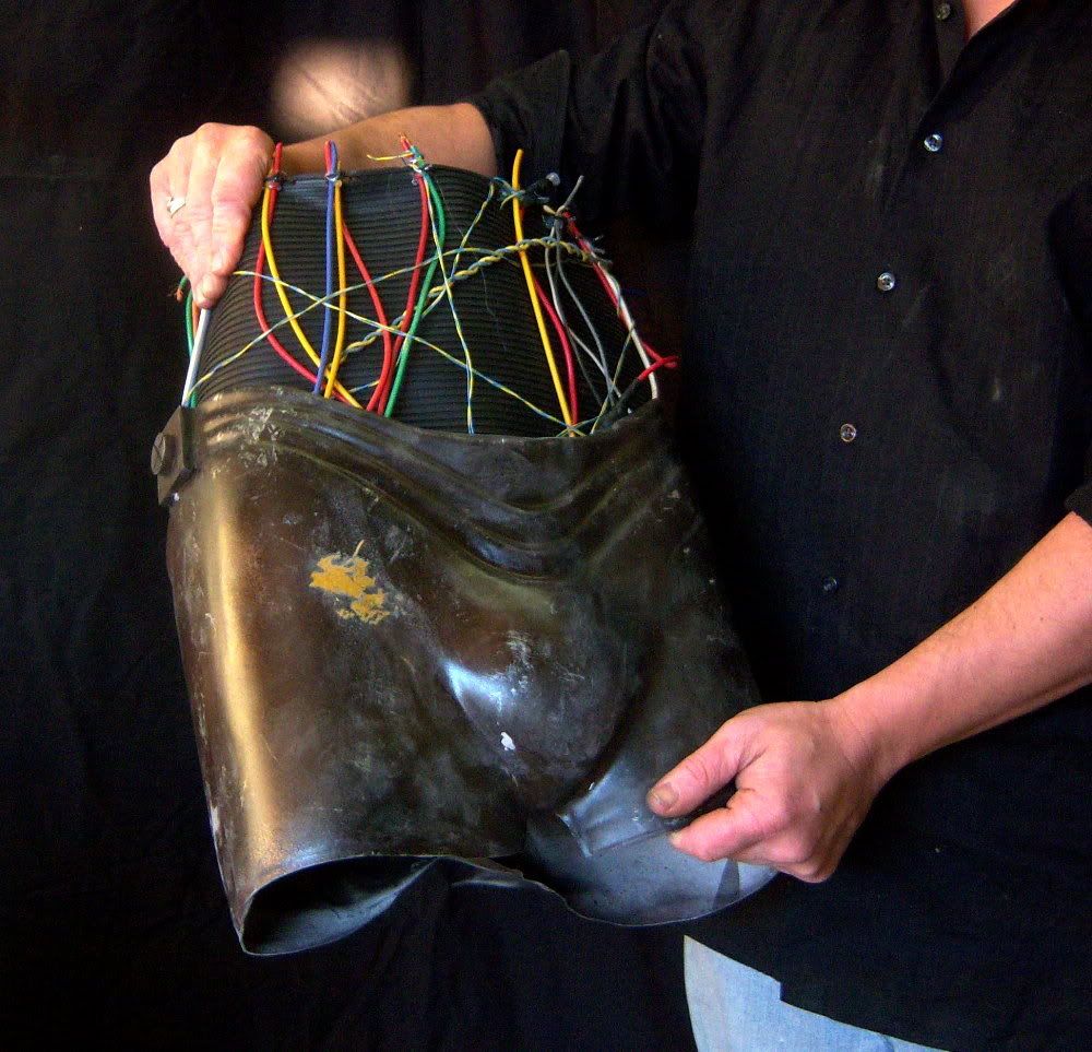
RIBBED RUBBER MID SECTION
COMING SOON..........
THIGHS
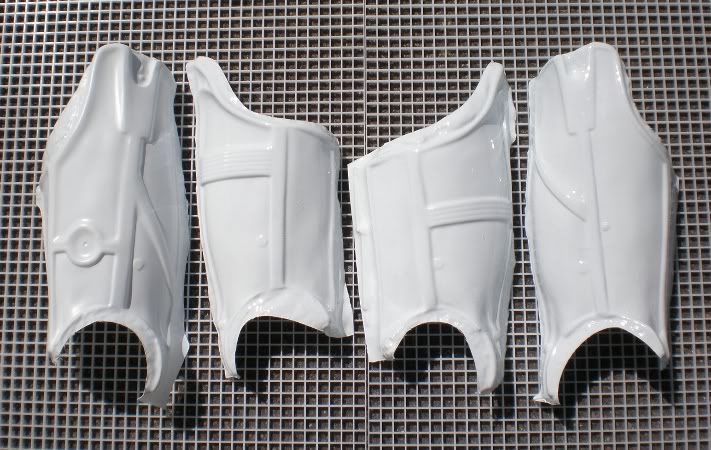
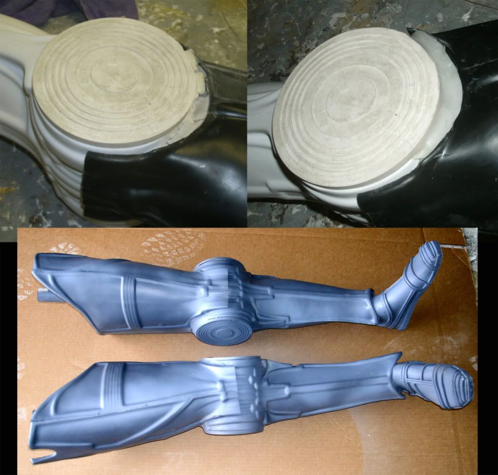
Trim the thigh pieces as shown. The trimline is very easy to see on the kit pieces. Fit them together using painters tape to hold them. The legs need to be widened a little, and this is youir best opportunity to custom fit the legs to your legs if you are planning on buiding a wearable suit. I used black plastic of the legs shells and white plastic for the rear leg expansion piece to demonstrate how this looks. Spot glue/spray kick them.

Super glue/spray kick them to adhere, then re-enforce that with bondo & pvc cement. Use the belt sander to trim excess off the edges. (showing above)
SHINS
The SHINS go together just like the thighs. Trim them at the exposed trimline. Assemble the halves where the top overlaps the rear. Adhere using the same steps detailed for the other body parts.

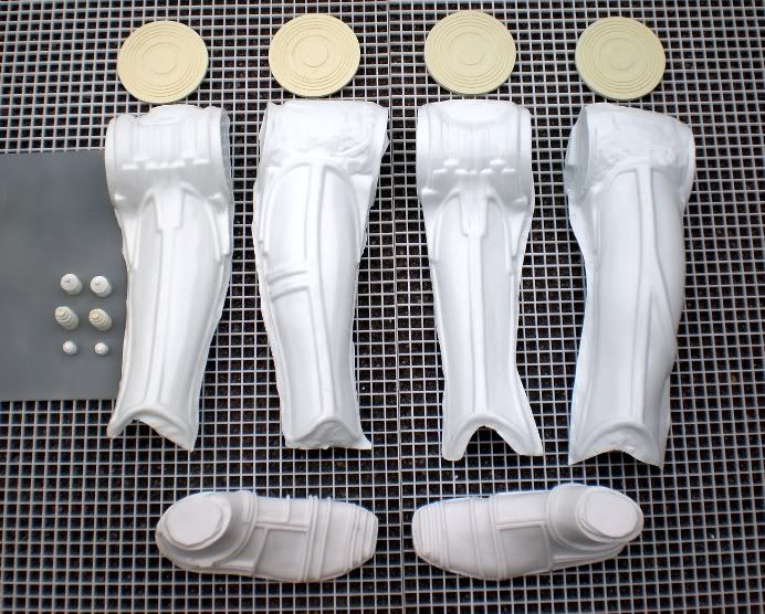
Sometimes you will end up with an uneven surface where the knee disks attach. Address this by filling the interiors of those areas with foam, then sand the disk area flat on a belt sander.

Then use superglue to adhere the 4 knee disks in place (showing above). Clamps help hold them tightly while the glue dries. Use a belt sander to trim any excess areas (last photo shows trimmed ankle area.
FEET
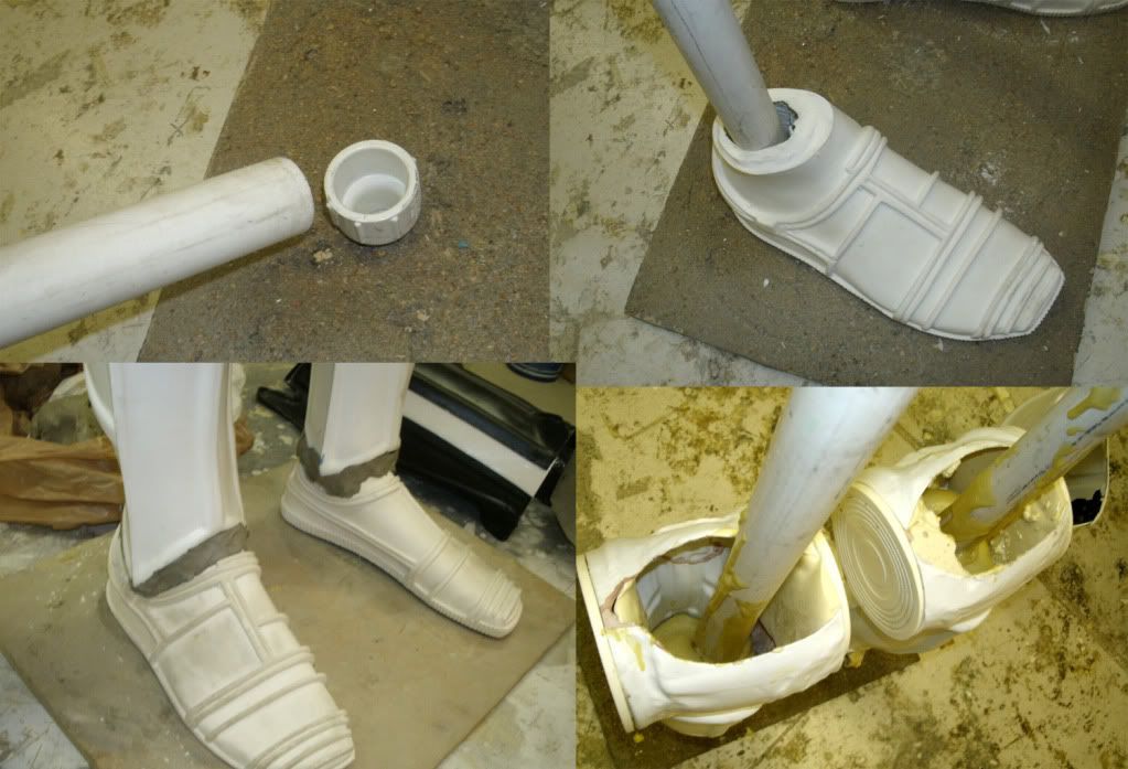
The Feet are simple. Just trim the bottom flashing on a belt sander.
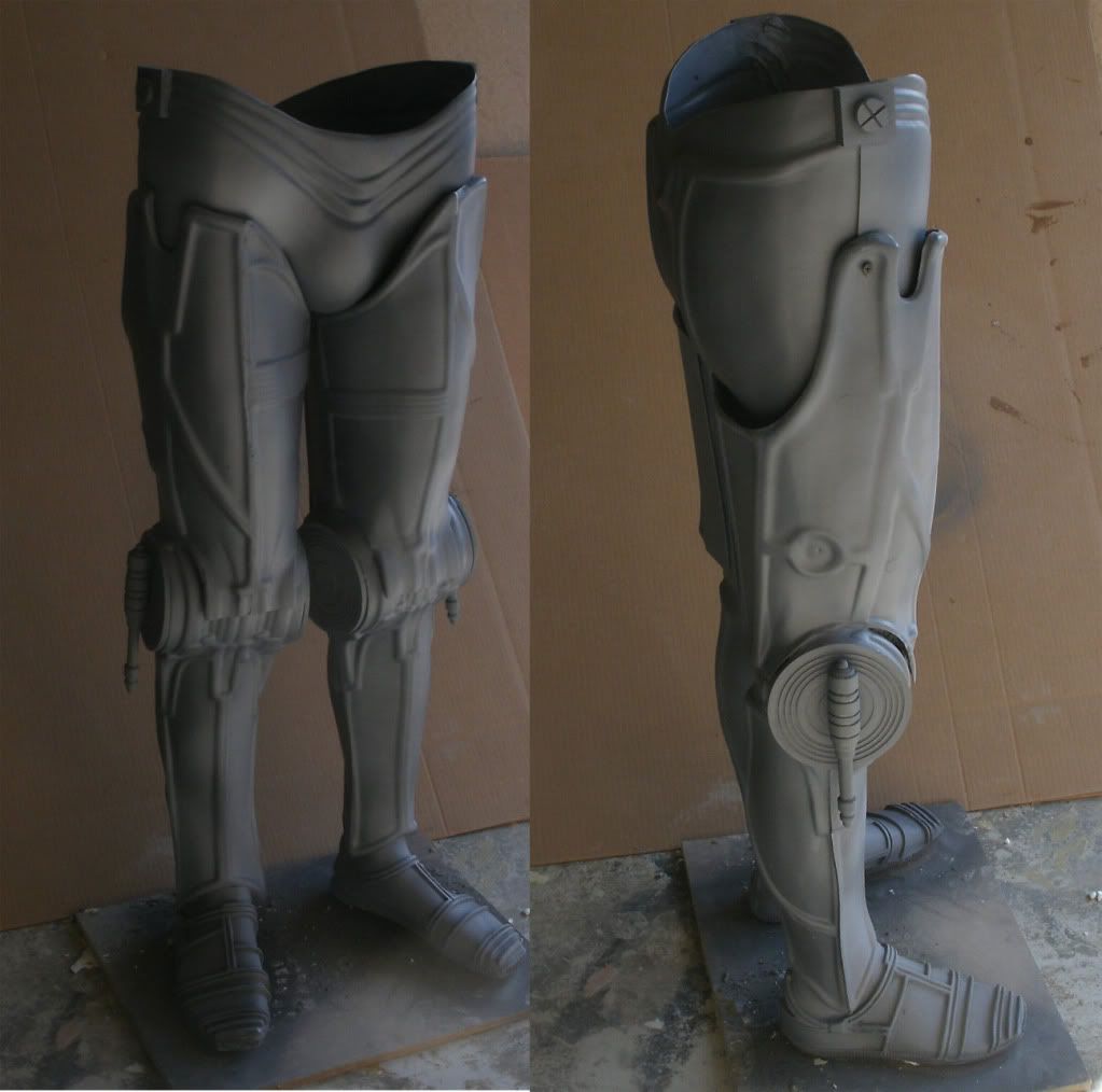
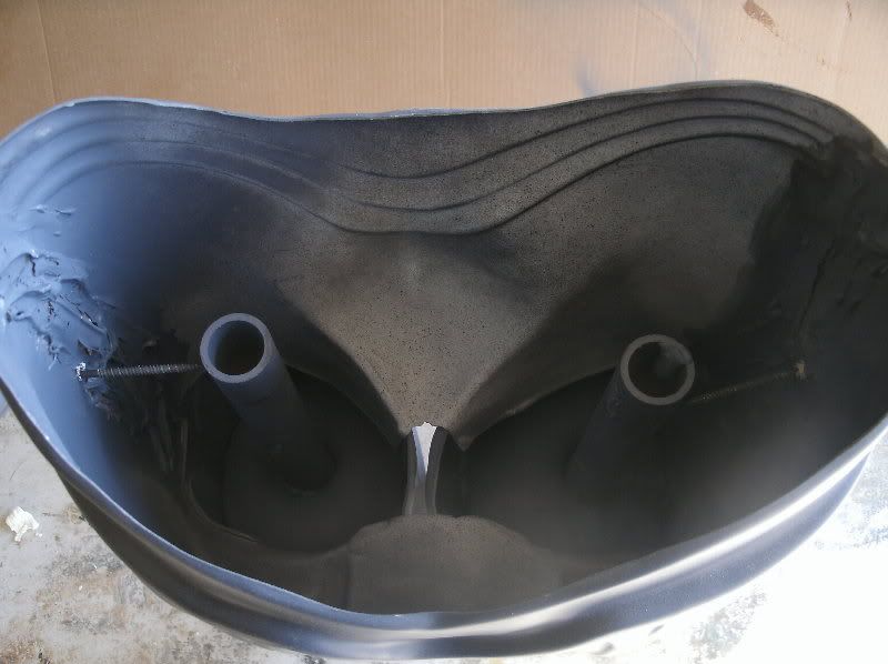
Now insert a 1" pvc pipe into the fitting throug the foot. Measure this pipe to about the top of the thigh (see photos below).
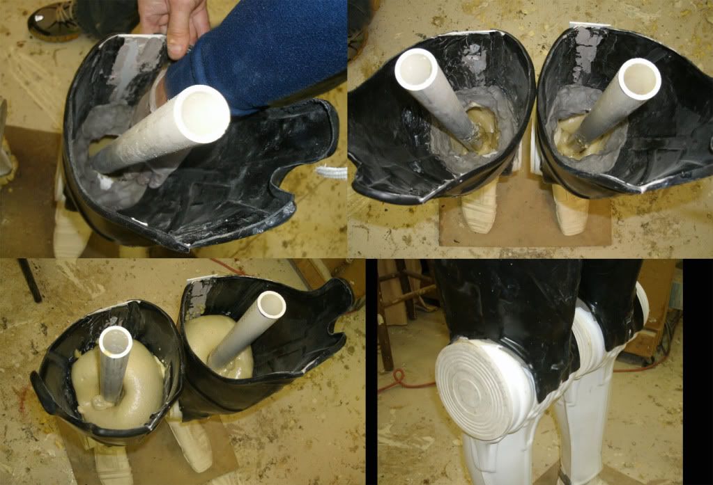
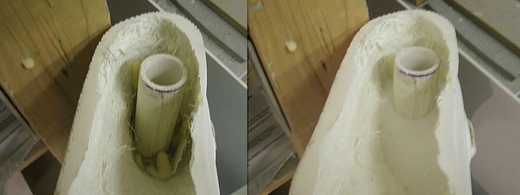
The posts in the interior of each foot can be re-enforced by filling in their connection area with resin or fiberglass. When doing this make sure to leave plenty of slack at the end of the post (where it will attach to your base).
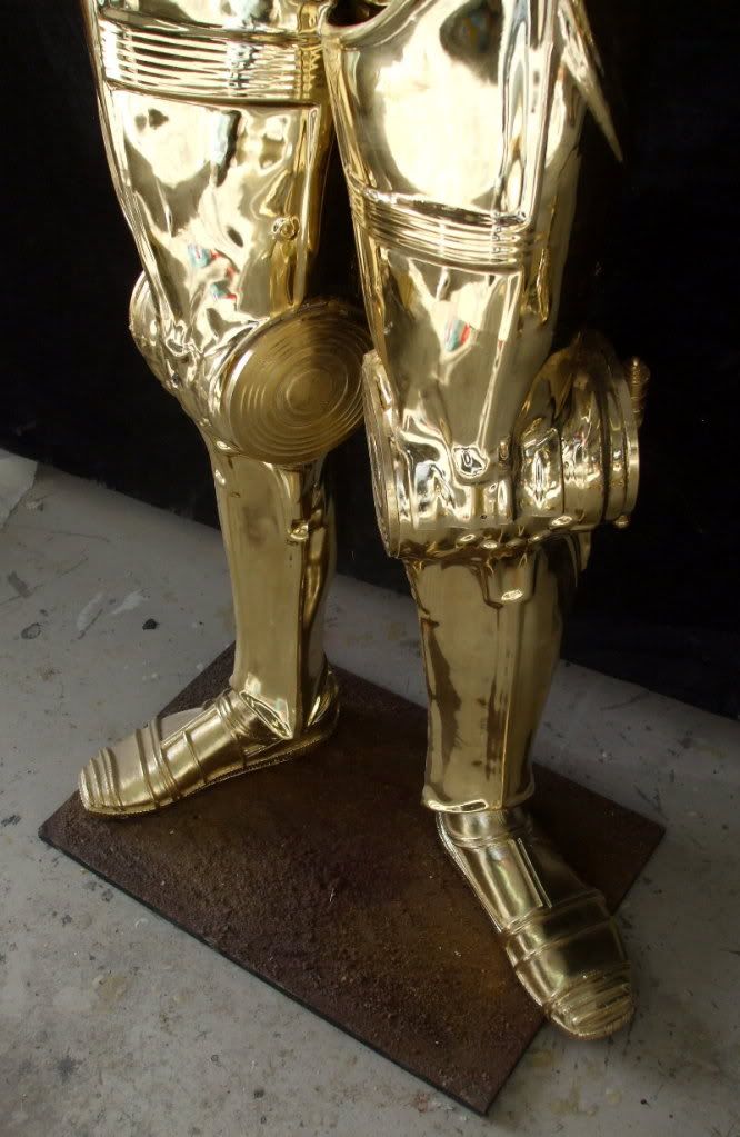
Fill any gaps in the knees with aves apoxie sclupt and YOU'RE DONE WITH THE LEGS!
DISPLAY BASE
PAINTING/PLATING
ELECTRONICS

