E.T. The Extra Terrestrial STARSHP Project
My name is Cristofer Adrian. I'm a special effects artist, first starting my career in model and prop production, then recently shifting my company into the digital special effects era.
In 2009 I had a chance to visit the ILM-built filming miniature used in E.T. The Extra Terrestrial. I ADORE this film and really love the ship design (designed by Ralph McQuarrie) so starting right there, while standing next to this awesome film-used model, I decided to build it when I got back to the studio. I took as many reference photos as I could manage, and a few weeks later I started planning out the construction of the model.
First, a little history on the design:
Ralph McQuarrie:
"Steven had a requirement for a space ship for E.T. He was at ILM one day and I talked with him for about five minutes - he said he would like to have ET’s space ship to look like Dr. Suess designed it. I thought that was kind of interesting, very off the wall."

Ralph Continues:
"I made about five or six sketches of space ships for it. He looked at them and picked one out and I made a painting of it. They built the model at ILM and looked almost exactly like the painting with all the features and the retractable lights, it was amazing. They did a beautiful job."

________________________________
SCRATCH BUILDING - PHONE HOME ONE
To start things off, I needed an egg shape. After looking around the net and hunting local shops and stores I realized IT'S NOT EASY SOURCING GIANT EGGS!! I settled on this ceramic egg:

The egg would translate into a model that was a fairly decent size - not too small, not too large. I began the modeling process by taking a mold on the egg. The hull of the ship is trunkated so I only needed about 3/4 of the egg. This mold would provide the castings I needed for the top and bottom hulls.

Once the casting was made, I cleaned up the egg as needed with fillers, and wrapped the bottom in styrene.

Working around a curved surface is REALLY HARD so it took some time and patience to map out the rings and holes that were needed. Calipers and templates were used to achieve symmetry.

Then I needed to create the panel lines in the upper hull.

This was done using a straight edge I mounted at the crown. This same metal straight edge was used as a guide to scribe the panel lines. TEDIOUS!!

Then it was time to start work on the bottom hull. I used the same ceramic egg RTV mold to create the shell, but had to shave it down at the top to reduce it's curve radius. I produced plastic templates that would provide the size and shape of the landing gear, and hatch insets.

Once I was happy with those templates, I drew them directly onto the casting and milled out the areas.

The hatchway and bulkheads were created with strip styrene.

The bottom of the craft is heavily textured so I applied a rough texture using a thickened acrylic compound.


Once the upper and lower hulls were at that stage, I began working on what I call the 'antenna array'. I started with a cone shape (created from rolled up styrene and fiberglass).
It was at that moment that I began understanding Ralph McQuarrie's theme when designing this ship: The shape of an EGG is a dominant repeating motif.
The cone is surrounded by egg shapes, SOOOO off I went to hobby lobby to collect some plastic eggs:


I pulled molds on the egg and cut the castings to the shape I needed, then countoured the leading edges to fit the cone.

I filled the gaps with epoxie putty and called it a day.

The upper and lower hulls are separated by disks. I had these machined in acrylic.
The hull plate disks are connected with an array of chips.

I sculpted a single chip out of renshape, took a single mold, then repeated the mold in sets, ending up with a mold that would produce over 100 chips in a single pass.

________________________________________________________________

When I was examining the ILM model, I saw that the middle hull ring is detailed with alien language symbols. AWESOME detail that you would never see on-screen!


To achieve this detail at this smaller scale, I decided I needed to have a laser cutter mill the alien letters for me. I drew out the glyphs is my CAD software and had them printed on .20 styrene.

Each symbol was carefully glued onto the ring, resulting in a pretty neat piece:

The landing feet are, surprise surprise, EGG SHAPES! I sculpted a protoytype in clay, molded and cast it, cleaned the master, molded again, and repeated the mold 3 times.


I drew out the contour blueprint for the engine bell and turned it on a lathe (special thanks to Dennis!)
The hull is surrounded by what I call "Landing Lamps". These shapes presented a challenge that was met and conquered on the lathe. Once a single lamp was turned, I detailed it with a dremel, cast it, and repeated the mold 8 times since there are eight of these surrounding the starship.


I made the ramp using styrene and plastruct struts.

This photo got me pumped. THE SHIP WAS STARTING TO TAKE SHAPE!!

The hull needed a ring that separated the skirt from the hull substrate. This was done using a plastruct beam.


These files were then sent to the laser cutting machine, a couple scaling issues were solved during the process.
The finished result was each landing gear assembly consists of three parts that are pinned together like this:

Once the design was test fitted and approved, I moved onto the molding stage. Here's Brinda helping set up the mold blocks:

Here's a look inside the prototype craft from the walkway ramp.


BUILDUP TUTORIAL

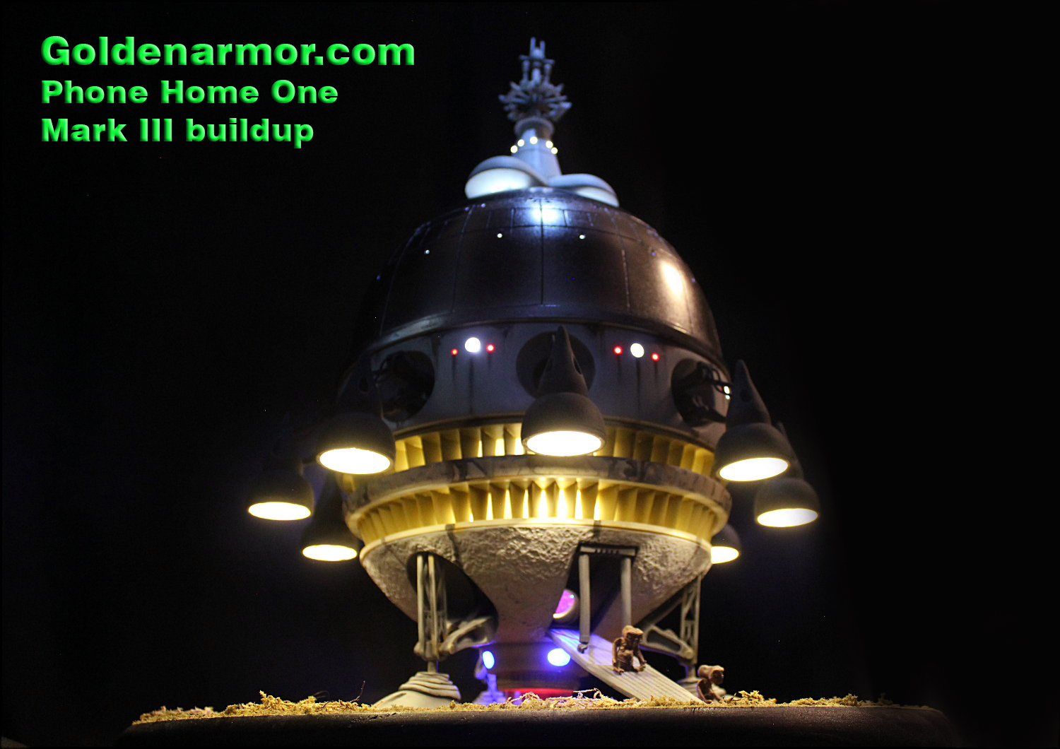
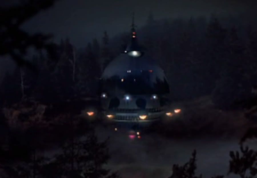
First some reference photos of the screen-used model. This will help your painting process.


I would suggest painting many of the pieces before you assemble. E.G. the hull separation chips are a textured rusty color. If you paint these first and the hull rings you won't need to bother with masking them later.


Use a sanding block to make sure you have a level surface on those chips. Now you can lay down the 'language ring'.

With the language ring in place, assemble the second level of 'chips'. Space them as evenly as possible (showing above) and be sure to glue them tall edge up to continue the upward angle (following the upward curve of the egg)

In the example showing here, Randy is customizing his ship with an advanced LED lighting system. A styrene ring is cut and placed on the lower end of the upper dome. This prevents light spill. You can do this option even if you aren't planning on lighting your kit.

And here's the main body fully assembled.

Here is a small mod to the engine bell. A small clear hemisphere is loaded into the engine nozzle to help diffuse the lighting effect.

Windows are drilled into the upper dome in the pattern showing below (refer to the screen used model for reference). Each whole vertical panel section is composed of one tall vertical rectangle (one window in the center), 3 vertical rectangles (no holes), and one horizontal rectangle (2 holes on the upper ends at the corners). So each section has three windows. Use a file to make them rectangular windows after you drill their location. They're really small so if you plan on lighting your model, it will probably be best to employ fiberoptics in those windows.
The lower window points downwards, the upper windows point sideways.
RAMP

The landing ramp is easy to assembly. Cut the provided grid screen to shape and glue on each ramp section. Then glue the ramps end to end like this:


COMING NEXT:
Assembling the 8 lamp engines. Then final assembly, and PAINTING GUIDE.
TO BE CONTINUED.........
PAINTING GUIDE
FROM THE TOP DOWN:
The ANTENNA ARRAY is off-white that has been weathered with dark brown and rust colors.
The DOME is a spraypaint type silver at the top cap. Then a VERY light bright silvery color (mix white and silver or use silver tape) on a horizontal band above the panel lights. Then the majority of the dome is REFLECTIVE CHROME. If you can, try to chrome plate this section. In the film it is mean to be a chrome reflection of the surrounding trees (to disguise it). Watch the film closely and you can see an environment reflection on this section. The filming miniature doesn't have as much as a chrome plate as it does a polished aluminum look so it's up to you how you want to apply silver to that area.
The best alternative other than chroming the dome (ask me, I can do this for you), you can use ALCAD to achieve a highly reflective polished suface. The FLAT PLASTRUCT BAND that separates the dome from the dome skirt is ALUMINUM silver.

The DOME SKIRT is off-white (a shell white) that has been weathered with browns, blacks and rust colors. Be sure to add on those heavy dark streaks underneath the light ports. The INSIDES of the white light ports is relective silver. (the film used Dome looks like it was machined from aluminum).

If you're not illuminating your model, paint the two small light ports red or insert tiny red marbles to mimic LEDs.

The LAMP GEAR ASSEMLY appears to be a mix of greys, greens and blues. Just mix your colors until you feel you match these photos. When you paint them, be sure to use ALOT of texture in your paint. I suggest adding in sand or even real dirt into your paint to get that bumpy texture. You might also want to add a little r.o. scale moss with some clear glue to the surface to make them even grimer. Have fun!
THE CHIPS. All the chips that separate the hulls are a rusty/orange color.
LANGUAGE RING is a bright silver that appears to have a very slight tint of copper. Use a VERY light touch of transparent copper paint when you tint it. It's barely colors it.
The LOWEST FLAT HULL DISK is similar to the language ring, except it's a tad bit more COPPERY.
The BOTTOM HULL is off white, and weathered with dark greys Use a sponge to when you apply the weathering to give it a random weathered feeling.
The LANDING GEAR are the same grey/blue/green you mixed for the lamps.
The LANDING FEET are the same as the landing gear except a bit of a lighter shade.
The LANDING RAMP is a charcoal grey.
The ENGINE BELL is the same color as your LOWEST FLAT HULL DISK. A coppery tinted silver.